By Kevin Custer
Concept & Use:
The use of a non directional coupler will aid in allowing you to see
response problems beyond your location.
Go here to read about this
concept.
Description / Specification:
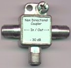
A non directional coupler sees forward and reflected power at the same
time, from either direction. A non directional coupler can be built
from a common drop splitter or dc. Use
this device in conjunction with a directional coupler to see differences
in response.
The non directional coupler is a device presenting a fairly light coupling to the circuit being measured, minimizing the loading effects. The tap output is attenuated by 30 dB. The In / Out connections pose minimal insertion loss. Nominal through loss is less than .4 dB. Nominal tap insertion loss is 30 dB. The tap output terminal impedance is approximately 75 ohms from DC to at least 450 MHz if the through port is properly terminated. The NDC presents about 20 dB return loss at the tap port. Careful construction practice and the use of small components may allow good response beyond 450 mcs.
Precaution:
Never connect the non directional coupler to cable or equipment that
poses AC or DC currents on the center conductor. The non directional
coupler is not designed to handle voltage on any terminal. Destruction
of the resistors will result.
Construction:
I start construction using a drop splitter in the "T" configuration.
Try to get one with epoxy holding the back cover as opposed to one that
is soldered in place. It is easier to remove the back of one that
is glued.
Remove the back cover by scraping the glue holding the back cover. The use of a small straight blade screwdriver, like a jewelers type, will aid in the removal. Be careful not to harm the cover or casting as you will be replacing the cover once the internal construction is done.
Gut out the internal components of the old splitter or DC and make the casting ready for the assembly of the new non directional tap.
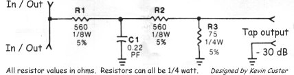
Refer to the schematic for understanding of part placement. Assemble the components into the gutted splitter casting by connecting the input and output of the coupler connectors together with a solid piece of wire. Then from the center of this wire connect the components as described in the schematic.
Parts List:
1) 1 old "T" style drop splitter or DC preferred, although any
style casting will work.
2) R1 and R2 are 560 ohm 1/8 or 1/4 watt, 5% carbon resistors.
3) R3 is a 75 ohm 1/4 watt, 5% carbon resistor.
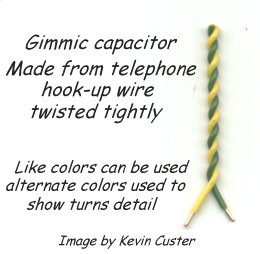
4) C1 is a .22 pF capacitor. This cap can be made by twisting
quality insulated small solid hookup wire together, and insuring the two
conductors are not shorted. This is referred to as a "gimmick" capacitor.
Click
here for a detail on a gimmick capacitor.
The gimmick should be trimmed to present the same tilt as what is being shown from the directional coupler. This is done by starting out with about an inch of twisted wire and cutting the gimmick off of the open end, a little at a time, to produce the correct capacitance. Be certain that the open end is not shorted or touching any of the metal casting. Orientation of the gimmick and the placement of the back cover also affects the capacitance of the homemade capacitor, so tune and test.... repeat if necessary.
The gimmick shown in the image (shown larger than actual size for detail) was built with standard bell hookup wire of approximately #24 conductors. Capacitance is about 1.2 pF per inch, so about a quarter inch is necessary to create the .22 pF needed.
Testing & Setup:
With either a true sweep or sweepless set-up, apply a 50
to 450 MHz sweep to the input of the dc-30 and take a reference on the
tap leg of the dc with the output and tap leg of the NDC terminated.
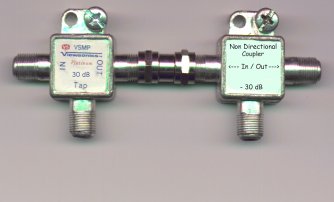
Connect a 30 dB directional coupler to the NDC as shown in this
picture. Now connect the sweep receiver to the tap leg of the
NDC and terminate the down leg of the dc. With the output of the
NDC terminated, adjust the gimmick to give the same tilt as seen in the
normalized display taken from the tap leg of the dc. Part placement
and construction practice will affect overall accuracy. It may be
difficult to remove all of the negative tilt, and it is really not important
to remove this tilt as long as the response is flat. Since there is a tilt
feature on the Wavetek Stealth, nulling the tilt is easy. The concept
is to see differences in response, not differences in tilt.
Watching it work:
With the sweep connected as above to the input of the dc-30, remove
all terminators and connect a 2 foot piece of drop cable to the output
of the NDC, do not terminate the other end. Look at the response
on the dc-30 tap leg, it should be fairly good, near what was seen when
the dc was terminated. Now look at the response via the NDC tap,
the response should show gross problems, deep nulls and rounded peaks.
Now terminate the open end of the drop, the response should be nearly as
good as when viewed from the tap of the dc-30. Learn anything?
Now you know why pressure tap systems are a thing of the past. Since
modern directional taps are directional
coupled, response problems beyond a tap don't show up on the subscribers
drop.
This information is Copyrighted 1999 by Kevin Custer