Concept:
Many newer amplifiers use directional test points. Older stations
like the Jerrold SJ series uses non directional test points.
What's the difference? A directional test point is used on an
amplifier for a couple of reasons, one main reason is the fact that response
problems beyond a test point will not show up at the test point allowing
greater accuracy in balancing the amp. Another reason is to separate
inbound and outbound signals. It is also easier to create more signal
level from a TP (test point) by using a directional coupler rather than
a non directional coupler. This is because a DC doesn't create weird
frequency dependent loading
effects on the line under test, just flat insertion loss. A non directional
test point loads the line and can pose problems to the line under test
which may affect accuracy. This situation becomes worse as the isolation
between the line under test and the TP output lessens. This is the
reason Jerrold created the SPD-30, or "speedy 30." A speedy 30 creates
a 30 down bi directional test point from a point within the amplifier that
connects to the input or output signal. This signal is AC [RF]
coupled to stop power from reaching the speedy 30. A value of 30
dB was chosen to allow reasonable level to reach the meter without loading
the line under test too much; a good compromise.
A station using a non directional TP allows the technician to see both forward and reverse signals at the same time. This situation allows only one TP to be used for forward and reverse, but there is a problem. Let's say you are balancing a forward amplifier with a non directional TP, and the plant beyond you is faulty. You may not (probably are not) setting up the amplifier correctly due to reflections from the bad cable or passive. This SWR or reflected power will cause constructive and destructive interference to occur. The relationship to the response seen at the TP is directly related to the distance to the fault and the frequencies involved. Reflections can add or subtract to the actual levels being developed by the amplifier, thus you may be setting up the amplifier incorrectly, this is especially true if you balance on one or two carriers, and don't take into account the others.
Non directional TP's allow you to see reflections from plant beyond the amplifier. So does this mean you can "see" beyond an amplifier when sweeping? It most certainly does if the test points are non directional. There are many so called engineers that say you cannot sweep beyond the location you are at, but these people don't really understand forward and reflected power and non directional test points.
Since non directional TP's allow you to see the response beyond you, how do you know you are setting up the amp correctly? The use of a directional TP is usually available in stations employing non directional TP's. Where you ask?, the output of the trunk module is usually DC'ed to drive the bridger and/or AGC module. This DC'ed output is a good spot for testing actual trunk levels, however you must compensate for the value of the DC and possibly the 2 way splitter in the motherboard, if installed, as in a Magnavox motherboard. Jerrold SJ trunk modules usually deliver a signal that is down 11 dB, so a 11 dB TP compensation is used, and no "Speedy 30" is needed. In older Magnavox stations, the value of the DC is determined by what trunk module is being used. If a 5T330 is used, a DC 11 is installed in the trunk module. This signal is cut by an additional 4 dB by the existence of the 2 way splitter in the motherboard. Since the 2 way feeds the bridger and the Complete Control (agc) module, a combined TP compensation of 15 dB is used. In Magnavox equipment, other values of DC's are used in different trunk modules, and they need compensated accordingly. In high gain models, there also may exist a pad to create proper levels to the bridger and / or CC module, so again compensation needs addressed.
Anyway, the concept here is to remove the bridger and use the DC'ed signal to set up the trunk amp, then look at the response both from the directional and non directional TP's. When the levels and response on both TP's are the same or very close, it is safe to assume that the plant beyond you is good. If the two TP's read differently (assuming compensations are corrected) response problems exist beyond the amp and the leg should be shot with a TDR to find the bad cable or passive. If the response is bad on the directional TP, it is safe to assume that there is a problem before you or where you are at.
This concept of using both directional and non directional TP's allows the technician to see if the problem is before you, where you are now, or after.
What about the feeder?........
Since most older stations use some form of feeder maker (feeder or
distribution splitter) that has a non directional TP on it, how do you
know that you are setting up the bridger correctly? This can be accomplished
several ways. The easiest way is to terminate an unused port (if
available) and deliver signal to it by temporarily replacing the feeder
maker (FM) with one that only feeds the term. Simply set up the bridger
into the term pin and then replace the feeder maker with the appropriate
one. If the levels read the same as when signal was applied to only
the term, the response beyond the amplifier in the feeders are probably
ok. If the levels read differently, response problems may exist on
one or all of the feeder legs. So how do you set up a bridger if
all the ports are being used? I remove the FM and use a drop/HE directional
coupler fed from the output port of the bridger, (input to FM). Simply
terminate the DC and read the signal from the tap leg. Use the appropriate
TP compensation and set up the bridger into the terminated DC. After
setting up the bridger with this arrangement, reinstall the appropriate
feeder maker. In both scenarios, if problems exist, disregard the
level being shown on the feeder maker, as you have set up the amp or bridger
correctly from the DC.
Now that you know how to determine the existence of problems beyond
a station, how do you track down which feeder is creating the problem?
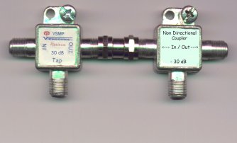
I build a simple device using
a drop/ HE directional coupler and a non directional coupler. Since
non directional couplers are difficult to come by, I simply build one from
a drop splitter. I use this arrangement to temporarily replace the
feeder maker. The use of this device will allow you to swiftly balance
the bridger correctly and then test each individual feeder for response
problems. If the feeder you are testing presents the same levels
and response on both the directional and non directional couplers, it is
safe to assume no problems exist to the next active or term tap in that
leg. If the two couplers read differently, the leg being fed has
response problems that need addressed. Many times the existence of
an incorrect feeder maker is actually the problem because someone put a
FM-3 in where a FM-2 should have been used.
Older line extenders, especially Magnavox, use a non directional TP built into the housing casting. These have a high error rate and the use of a tap connected via a housing to housing is a good way to verify correct output levels. Simply add the tap value to the tap levels to come up with the actual amplifier output level. Or use the tap value as the TP compensation value. In essence, the tap gives you a directional coupled test point.
So how do you look at response ahead of you in newer equipment that
only has directional test points?
The use of a NDC can be applied to newer equipment by using modified
tap and splitter plates to allow the connection of these testing devices.
Another concept can be applied to newer stuff like the C-Cor fiber to
feeder distribution systems.
Click here to view an image
of a modified feeder splitter for newer 550 & 750 meg C-Cor equipment
that allows you to separate the feeder legs and use the directional and
non directional coupler. This device allows the amplifiers output
to be connected to test devices and also allows the signal to be routed
to one particular port. This concept can be applied to various signal
steering devices in a variety of equipment.
Summary:
Using Non Directional test points allow you to see problems beyond
you. This is beneficial because you can start looking for the problem immediately
after setting up and sweeping the amp via the directional TP. It certainly
is nice to know if you are going to have a problem before you get to the
next amp, LE or term. Shooting the bad leg with a TDR usually will
tell the tale on the bad spot. Go here to build
a non directional coupler.
The information presented here is Copyrighted 1999 by Kevin Custer