By Kevin Custer
Concept & Use:
The use of this universal line splitter (ULS) plate will allow you
to separate signals to allow testing of plant without needing to remove
cables from a splitter, DC, or power inserter. This device can be
placed into the line, at a convenient place, to allow response tests and
the attachment of a TDR to the plant.
Description:
This ULS plate can be configured to temporarily replace any line splitter,
DC or power inserter. This is done by connecting common drop passives
to the appropriate F connections. The plate will also allow the use
of a non directional coupler to be placed into the system to see response
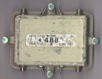
problems in separate lines leading from the splitter. The plate shown
here was designed to be used in a Magnavox system, however any style plate
can be configured similarly to allow testing.
The ULS plate allows configuration of the AC voltage to pass from any port to any port or no ports at all. AC voltage is blocked to the F connections to allow common drop passives and a non directional coupler (NDC) to be used without the risk of damage. A TDR can also be connected directly to the F ports to allow easy shooting of each independent line.
Advantages:
The use of this device will allow you to keep as much of the plant
on as possible by only interrupting the line under test. Quick testing
of the affected line will allow the determination of the damage.
Since the plate will allow a TDR to be connected easily several different
tests can be performed by the use of this one plate.
Construction:
I construct the ULS plate from a 3 way line splitter plate .
The use of a 3 way allows all possibilities since all four seizure connection
mechanisms exist. Simply remove the plate from the casting, and then
remove the circuit board and gut a 3 way line splitter. Be careful
to gut only the RF path and allow the original AC chokes and decoupling
components to remain.
Drill the casting to allow the addition of the AC steering switches
and the F connectors to be mounted. Insure you are not installing
the added components in an area that will not allow the reassembly of the
board into the plate. View
the images to see how the added switches and F connectors are mounted.
If the AC shorting bars or jumpers exist, remove them. The switches
will be wired to allow power configuration. Connect a 750 pF mylar
capacitor, salvaged from the gutting of the plate, from the seizure connection
mechanism to the appropriate F connector using the shortest possible path.
This is done in all four locations. In a Magnavox plate these capacitors
must exist sandwiched between the circuit board and the plate casting.
This presents a construction problem as the capacitor needs soldered to
the seizure receptacle. I drill a small hole right next to the seizure
receptacle to allow an added length of wire to be passed through the board
as it is reassembled. Since it is difficult to align these caps to
pass through the holes, the added lengths of wire allow the threading through
the board while the board is placed back onto the plate. These added
wire lengths are pulled tight and soldered directly to the seizure receptacle
after the board is secured to the plate. The excess length is then
cut off.
The information presented here is Copyrighted 1999 by Kevin Custer